To create the signalling system for Collingwood, the system is designed around a computer programme called Java Model Rail Interface or JMRI and the Model Electronics Railway Groups (MERG) ‘CBUS’ layout control system.
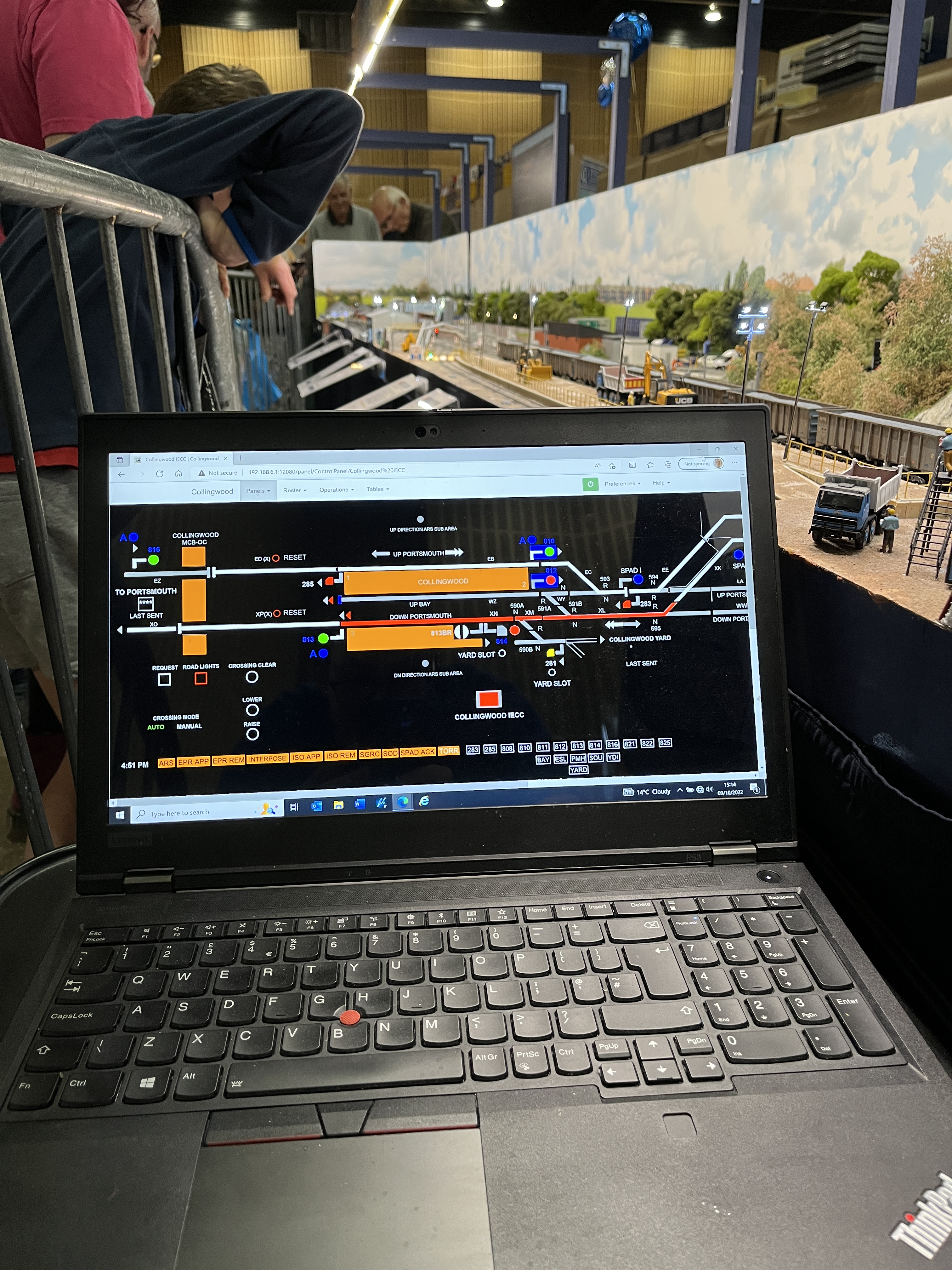
For Collingwood, JMRI is being run using a Raspberry Pi Micro-Computer which is then displayed on an ultra-wide signalling screen with the signaller using a Laptop connected to the Raspberry Pi via the latter’s own Wi-Fi network and JMRI’s internal web server function to interact with JMRI.

‘VDU Signalling Control System’

JMRI a free, open source, computer programme that can be used to control various model railway functions, including automation tools. There are two core elements that Collingwood uses, the one that drives the VSCS is ‘Panel Pro’, a tool within the software that allows a modeller to create customer control panels from which to control their layout, and ‘Logix’, the element that can be used to write logic statements from which a layout can be controlled.
Panel Pro, via it’s ‘control panel’ editor, can use custom graphics to re-create any panel and forms the IECC workstation for Collingwood. The graphics were created using a graphics package called ‘Serif Draw Plus’, however, if you are skilled at Paint, then you should be able to create the necessary graphics. I first drew out the panel as a whole to see what it would look like and how I would carve it up to use in JMRI. The graphics were based on those defined in RSSB and Network Rail standards for IECC symbols, but slightly modified to make the screen more visually interesting for an exhibition layout. The graphics were drawn at a scale which seemed right when display on the screen seen behind the layout, and then exported as .GIF files for use in JMRI. Careful thought had to put into the creation of the graphics to ensure they animated currently in JMRI.
It should be noted that as development is continuing all the time in railway signalling and VSCS workstations allow more functionality than in physical panels, new symbols and animation are added all the time, so my VSCS workstation might not be fully compliant with the current standards. Equally, as JMRI has it’s limitations on what can be animated and controlled, there are compromises with some aspects of the operation of the workstation, but it is 95% as per the real thing.
The ‘Interlocking’
The interlocking is driven through the other core element within JMRI, that being the software’s ‘Logix’ tool. This is a section of the Panel Pro element of the software whereby the user can write simple or complex logic statements in a simple graphical interface through which they can control various elements of their layout.
It should be noted that I use the ‘classic’ ‘Logix’ rather than the new ‘Logix NG’ within the newest releases of JMRI. I find this new ‘Logix NG’ is far from user friendly and the documentation poor if you are not used to writing computer code (at least in my opinion)
For Collingwood, ‘Logix’ is a very powerful tool because it can be used to write the ‘nested’ ‘IF’ statements that are used in interlocking logic.
The actual interlocking logic that is replicated within the Collingwood ‘Logix’ is based around British Railways SW67 style route relay circuitry because I had access to typical circuit diagrams for the system and I have been trained to work with SW67 style circuitry. Whilst this means that Collingwood does not replicate actual CBI data, the functionality and principles are maintained, and it acts to the audience as a real VSCS & CBI interlocking. Sadly, as the circuits I have used to create my interlocking data are still in use on the network today, I can’t share details on them to maintain the security and integrity of them.
Layout Interface

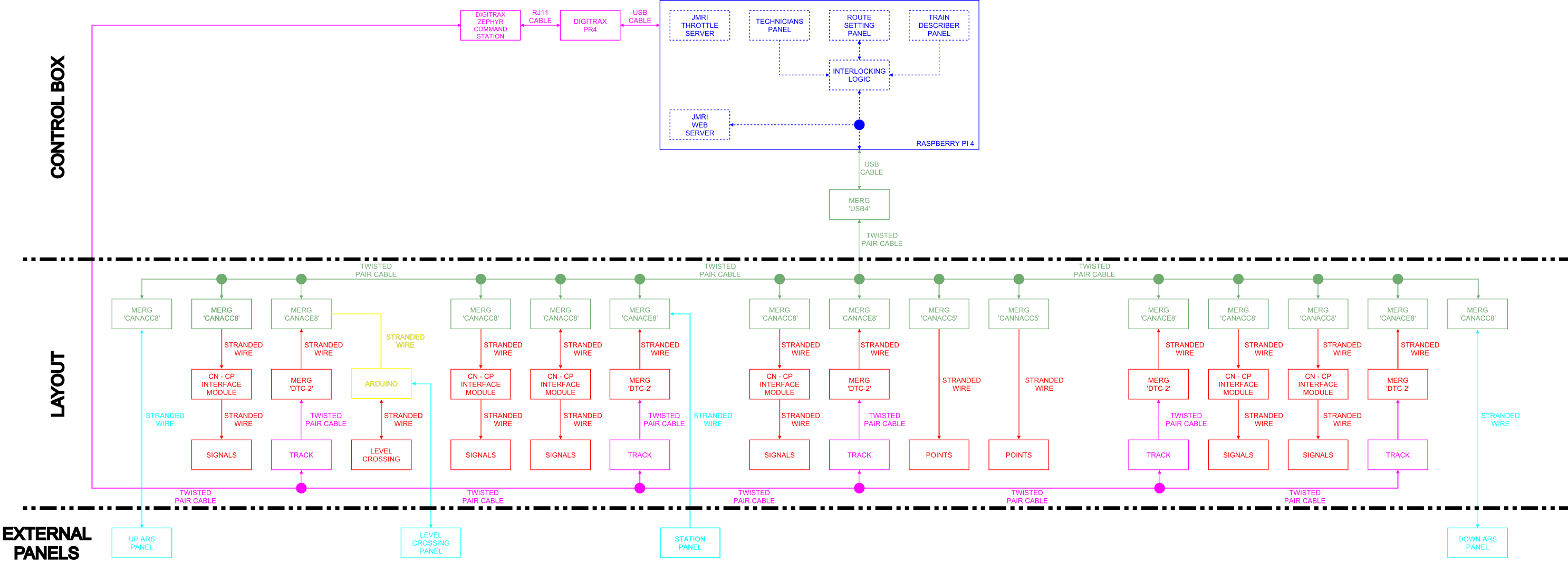
To connect the layout to the JMRI system, Collingwood uses the Model Railway Electronic Group (MERG) ‘CBUS’ layout control system.
The system consists of several modules made up of input and output modules which are connected through a network that uses CANBUS language. The Raspberry Pi that contains the IECC and interlocking listens and sends CBUS messages between it and the CBUS network via a USB interface. Input Modules can be configured to send specific CBUS messages in response to input from the layout, whilst Output Modules can be configured to listen for specific CBUS messages and then activate outputs for the layout. This is a very similar to how DCC works.
Signals, Track Circuits & Points
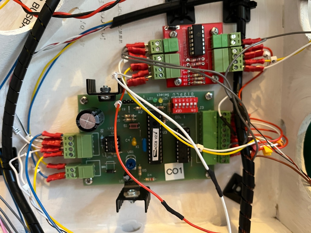
The signals on the layout are custom built by Absolute Aspects based on real signals at Fareham, but modified slightly to the restrictions on the layout. The signals are constructed from brass and white metal and use surface mount LEDs. A problem found interfacing these signals with the MERG CBUS system is that the signals are wired as common negative (or cathode) whereas the MERG CBUS output modules are designed to work with common positive (or anode) signals. To get around this, Collingwood has extra interface modules between the CBUS output modules and signals using LM324 Integrated Circuits, designed by MERG members and produced with the help of a friend of mine.
A key part of a signalling system is the requirement to be able to detect trains. On Collingwood, this is done via MERG ‘DTC’ DCC current detection modules. These work by one of the track feed wires for a section of track being wound around a detection coil, the modules detecting the magnetic field that is generated as current is drawn through the track feed. This means that all vehicles must be capable of drawing a current when on the layout, for powered vehicles this is done by the DCC decoders, but unpowered vehicles require a 10K ohm resister being placed across the axles to draw a very small current


The points on the layout are Circuitron Tortoise Point Motors which are driven via special CBUS modules for driving stall type point motors. I have decided not to fit any form of point detection to maintain reliability, but all points use one of the internal microswitches on the motors to switch the feed for the ‘frog’ of the point.


It should be noted that I have taken the time and effort to convert all the modules and connections to ‘Plug and Play’ style connections, this has helped immensely when I have had to undertake repair or replacement of modules

Block schematic system architecture: would it be possible to see a sharper resolution diagram?
Thanks
LikeLike
Hi Sumit, it should be a large resolution, I’ll investigate and get back to you. Simon
LikeLike