It came to my attention a couple of weeks ago that West Hill Wagon Works released a set of Power Change-Over & High Speed Coasting Signage for ‘OO’ and I thought that it would be interesting to explain what this signage is and how to position it on a model.
To explain a little bit of my knowledge on the subject, I was the lead designer, along with a colleague of mine in Network Rail Design Delivery, on the projects to provide Power Change-Over signage for the Class 800 / Class 802 fleets & the ill-fated Class 769 fleets on Western Route over the last 5 years or so.
History
The first of what I’m going to call ‘Power Change-Over’ (PCO) signage was in 1993 in readiness for operation of Class 373 ‘Eurostar’ sets that were required to change between the 25kV 50Hz AC overhead electric supply of the Channel Tunnel Rail Link and the 750v DC top contact conductor rail electrical supply of the Southern Region. These signs were based on the ones in use on the French Railway System. The signs were installed at Dollands Moor, between Southfleet & Fawkham Junctions and between Kensington & North Pole.
These signs were subsequently adopted for use as ‘High Speed Coasting’ (HSC) signs under new rules which were introduced in august 2011 to allow AC overhead electric trains to coast with their pantographs down through damaged areas. These signs are temporary & are installed much like a Temporary or Emergency Speed Restrictions around an area where the overhead Line has been damaged or disconnected. Additionally, these HSC signs included a pair of new signs. These signs have mostly been used on the East Coast due to it’s frequent de-wirement / damage events.
During the run up to the introduction of the long awaited HST-replacement Class 800 & Class 802 fleets on the Great Western Mainline, it was realised that a need to provide signage to back up the Automatic Power Change-Over system on these new ‘Bi-Mode’ trains was required. Network Rail Design Delivery in Reading led the development of the signage requirements and positioning rules and delivered the initial installation at Maidenhead in october 2017, less than two months after the start of the development period. These signs were subsequently rolled out across Western as the electrification advanced west as well as on the East Coast with their first installation in July 2017.
During 2019, Greater Anglia started to introduce their own Bi-Mode Class 755 units that meant an introduction of further ‘stationary’ power change-over signage, developed in conjunction with GWR.

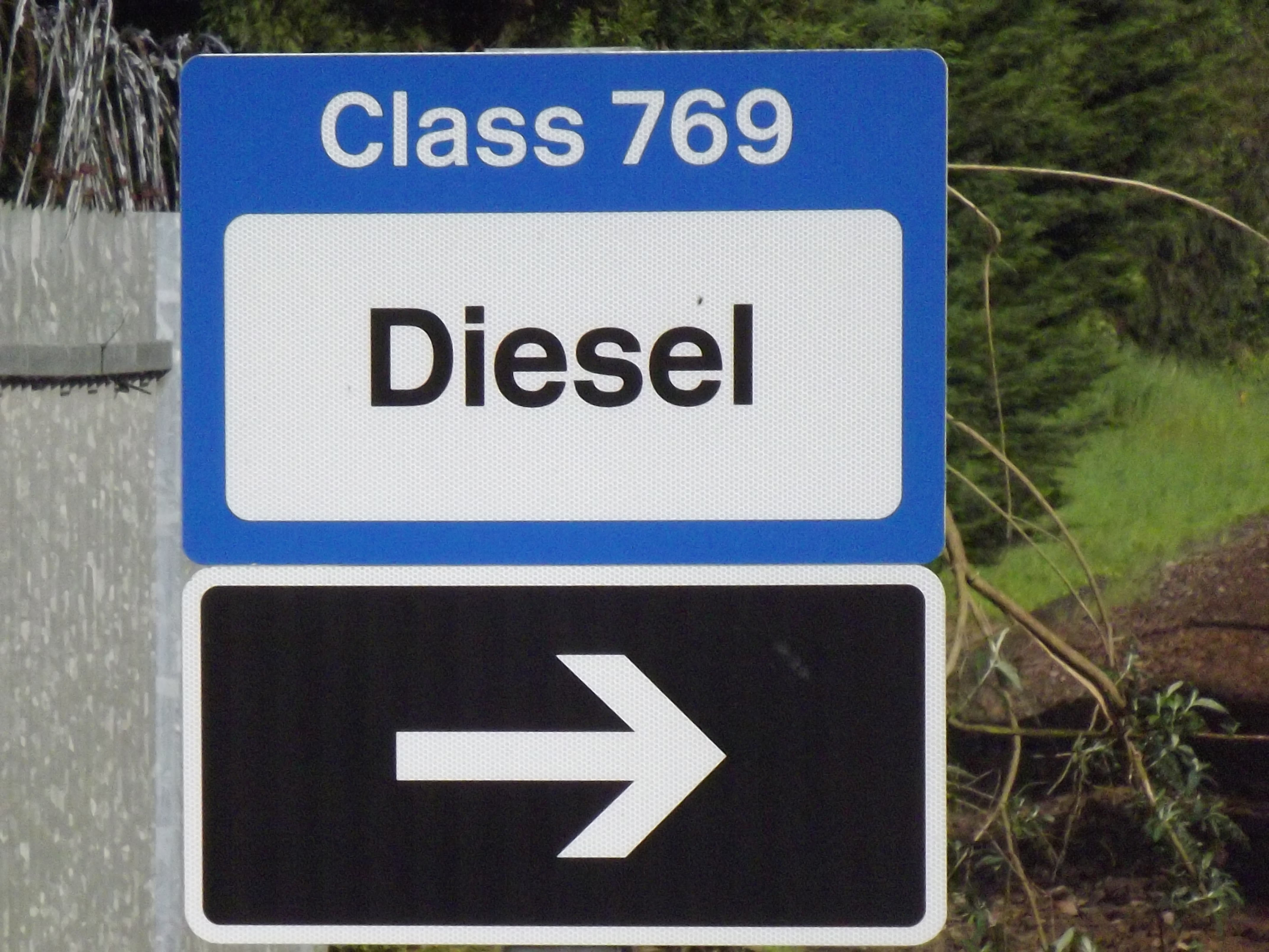
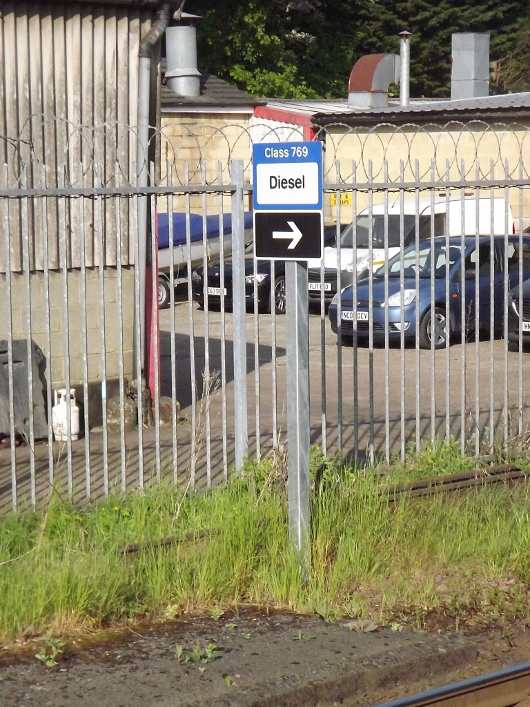
Finally, to support the introduction of Class 769/9 Tri-Mode Multiple Units on the ‘North Downs’ line between Reading and Redhill, further PCO signage was installed in December 2021, however the cancellation of the project in 2023 has seen these signs removed without ever being used by a revenue earning service.
The Signs
As discussed earlier, the signs are based on those used on the continent:
| Sign | Dsecription | Dimensions | Channel Tunnel Meaning | High Speed Coasting Meaning | Power Change-Over Meaning |
|---|---|---|---|---|---|
 | ‘Warning of Traction Change-Over’ | 600mm x 600mm | Instruction to driver to open circuit breakers & lower panto-graph (if changing to DC) or raise third rail shoes (if changing to AC) | Not Used | Warns the driver of a Power Change-Over site and to select ‘Coast’ on power controller |
 | ‘Advanced Lower Panto-graph’ | TBC | Not Used | Warns the driver of a High Speed Coasting Site | Not Used |
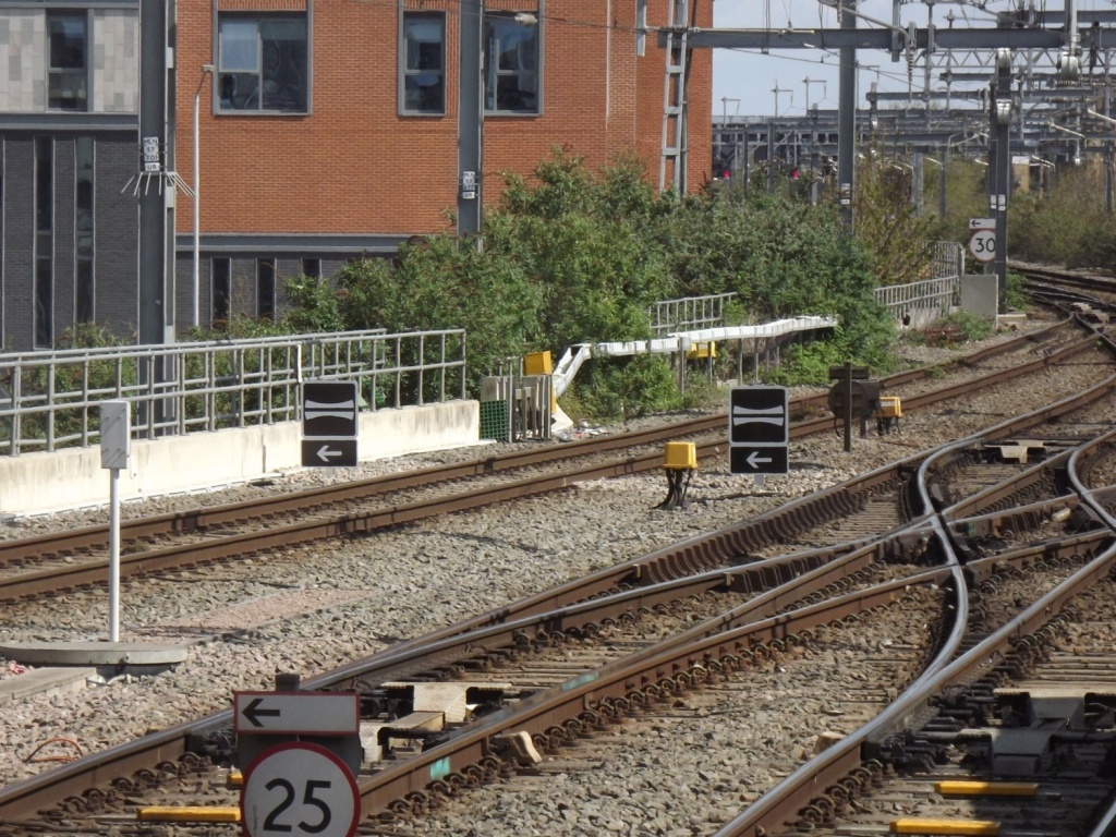
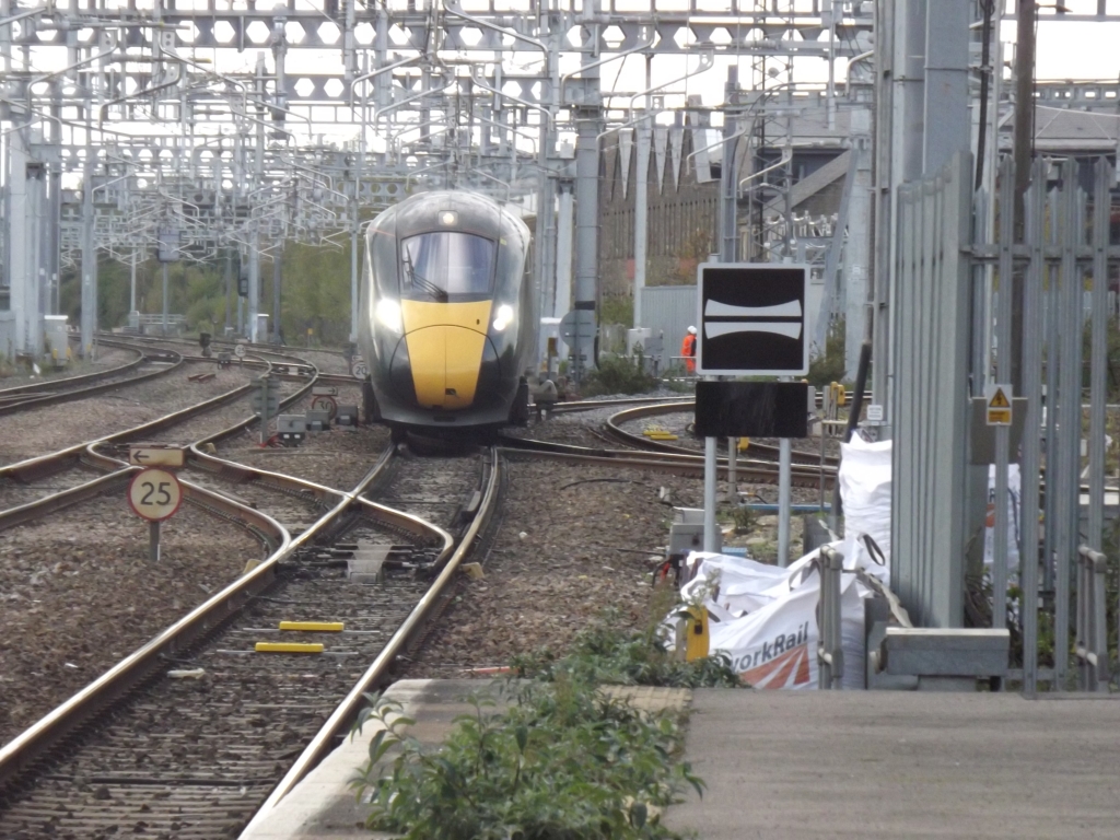
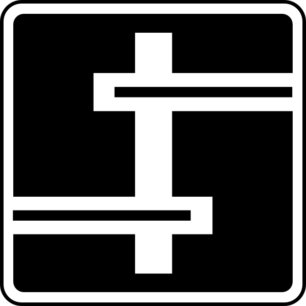
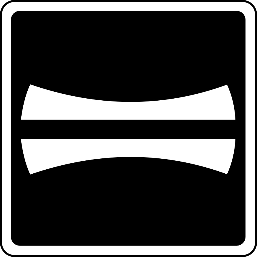 | ‘Lower Panto-graph’ | 900mm x 900mm or 600mm x 600mm | Instruction to driver to lower third rail shoe gear and ensure panto-graph is lowered | Instruction to driver to lower panto-graph’ and select ‘Coast’ on Power Controller | Instruction to driver to bring their train to a stand at once if panto-graph is not fully lowered upon reach sign |
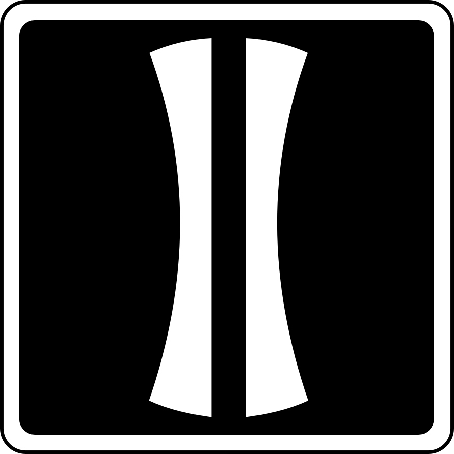 | ‘Raise Panto-graph’ | 900mm x 900mm or 600mm x 600mm | Instruction to Driver to raise panto-graph and ensure third rail shoe gear is raised | Instruction to driver to raise Panto-graph | Instruction to driver to raise Panto-graph / initiate change-over to AC electric when nose reaches sign |
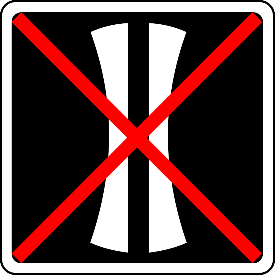 | ‘Do Not Raise Panto-graph’ | 900mm x 900mm or 600mm x 600mm | Not Used | Instruction to driver to not attempt to raise panto-graph beyond this point above 20mph | Instruction to driver to not attempt to raise panto-graph beyond this point above 20mph |
 | ‘Dynamic Power Change-Over Initiation’ | 600mm x 450 mm | Not Used | Not Used | Instruction to driver to initiate Power Change-Over to stated traction mode whilst on the move once nose reaches sign NOTE: Not used in change-overs to AC electric |
 | ‘Static Power Change-Over Initiation’ | 600mm x variable height | Not Used | Not Used | Instruction to driver to initiate Power Change-Over to stated traction mode whilst stationary at Stations |
 | ‘Abort’ | TBC | Instruction to Driver to bring train to a stand at once if Traction Change-Over has failed | Not Used | Not Used |
 | ‘Degraded Mode’ | TBC | Instruction to Driver to stop train at next appro-priate location if Traction Change-Over has failed | Not Used | Not Used |
Additional Signs used in Dynamic Power Change-Over may be provided with additional ‘white-on-black’ legends boards to indicate specific route or train that the Power Change-Over applies to:

Positioning
Positioning of these signs is fairly common across all three types of scenarios, although it should be noted that if any of the processes are to be undertaken statically, the following diagrams not to apply and no signage is provided except for possibly the Static Power Change-Over Signage.
In the case of ‘High Speed Coasting’, the positioning is as follows:
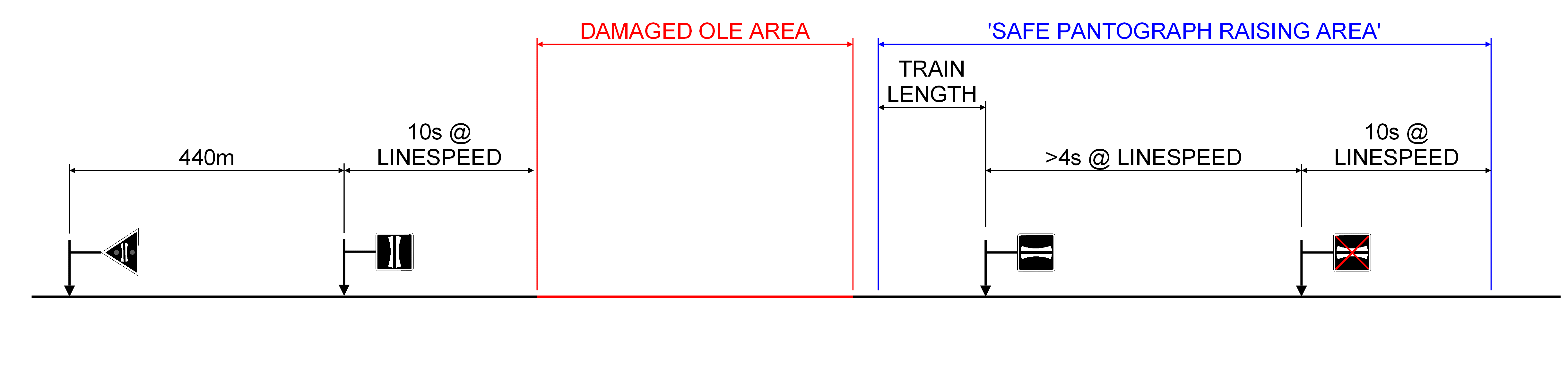
Whilst for Power Change-Over:

Please note that pantograph raising signage is referenced against a ‘Safe Pan Raising Area’, this is an area where pantograph raising can happen at Linespeed. The Safe Pan Raising area is made up of fairly straight, level, plain Overhead Line Equipment. If a driver wishes to raise their trains pantograph outside of this area, they must reduce speed to below 20mph to do so.
Where trains, such as the Class 373’s and Class 769’s can take power from the third rail, it must be ensured that the initiation sign is train length into the third rail area, so that all the third rail shoes are on the conductor rail.
Please note that the dimensions above are simplified for the modeller only and there are more detailed restrictions and positioning rules required in real life. Modellers should be reminded there are general positioning rules of signage around signals, if you are interested in what those are, see my book.
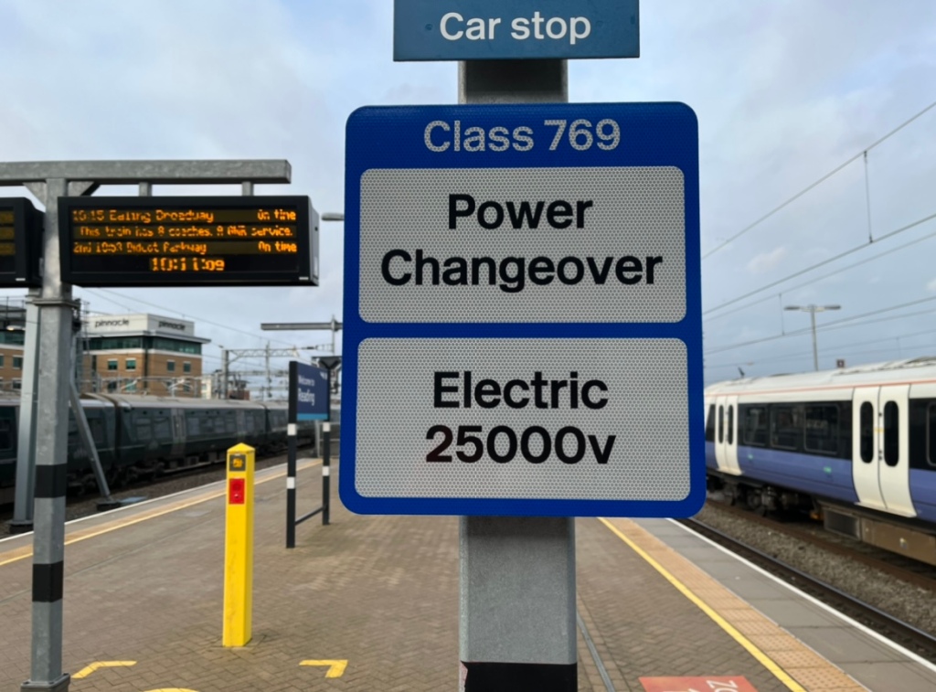
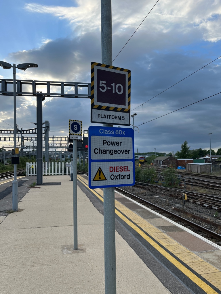
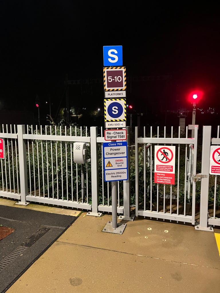
Where Power Change-Overs are done statically in a station for Class 755, Class 80x and Class 769/9 units, ‘Static Power Change-Over Initiation signs’ can be provided at relevant Car Stop Markers on the Platform. Below is a selection of the ones that were be found on Western


Modelling the Signage
Now with West Hill Wagon Works with releasing the signage, it makes it slightly easier, although the Power Change-Over Initiation signage has yet to be produced.
If you wish to produce your own signage, it should be easier to by scaling the signage down to your chosen scale and printing it out on matt photographic paper.
This can then be attached to a suitable post. For the large 900mm square signage, this should be a pair of posts due to their size. Whilst 600mm wide signage is suitable for single posts. Note that these should be square profile posts to prevent rotation.
For ease of construction, when we designed the Power Change-Over signage on the Western, we made extensive use of ‘uni-strut’ fixings and affixed signs onto the OLE masts themselves, albeit offset from the centre line of the structure to ensure the signs wasn’t more than 2500mm from the track.
I hope this explanation of Power Change-Over signage and with the release of Class 800s from Hornby in OO and Kato in N Gauge as well as Class 769s from Graham Farish in N Gauge and the forthcoming Class 755 from Hornby in OO (all available from retailers such as Kernow Model Rail Centre) has inspired you to add them to your layout.
